The Lawn Mower Wiring Diagram OEMs Won't Give You (PDF)
Read any lawn mower wiring diagram fast: the universal starting circuit labeled wire by wire, ignition-switch terminals, the ground wire, plus free no-login PDF
Written by Tony MaldonadoReviewed by Wade CoburnLast updated on September 10, 2026
When you buy through links on our site, we may earn an affiliate commission (at no extra charge), which we use to fund new product tests. Learn more.
Read it your way
Short on time? Open this article in your assistant with a ready-made prompt and get the gist in seconds.
Found this useful? Make us a preferred source so we show up in your Google results.
Turn the key, hear nothing, and the first thing you want is a picture of how the thing is wired.
Every riding mower runs the same four electrical loops, yet a lawn mower wiring diagram that actually labels each wire is strangely hard to find.
The engine makers publish a generic alternator sketch and point you to a manual, and the forums argue in fragments.
This guide gives you the whole starting circuit on one readable page, names every wire, walks the ground wire that trips up most no-start jobs, and hands you a free PDF with no login wall.
Lawn Mower Wiring Diagram: The Short Version
A lawn mower wiring diagram maps four loops that share one battery and one frame ground: starting (battery to solenoid to starter), charging (stator to regulator to battery), ignition and kill (key switch to coil), and safety interlock (seat, brake and PTO switches).
Read those four loops in order and almost any riding-mower electrical fault becomes a five-minute trace instead of a guessing game.
The single most misunderstood part is the small ground or kill wire on the coil, which stops the engine by grounding the ignition.
That one wire is covered in full below.
The Universal Starting Circuit at a Glance
The universal lawn mower wiring diagram below covers most riding mowers and lawn tractors built since the 1990s, because Briggs & Stratton, Kohler and Kawasaki engines all wire the starting circuit the same way.
Current leaves the battery positive, waits at the starter solenoid, and reaches the starter only when the key energizes the solenoid trigger and every safety switch is satisfied.
Learn this one picture and the brand-specific diagrams stop being intimidating. Here is the plain-language version of what the diagram shows, top to bottom.
The six lines below name each conductor in that order.
Battery positive feeds the solenoid large post and the ammeter or charge line.
The key switch B terminal is always hot from the battery.
Turning to START sends power out the S terminal to the solenoid small post.
The solenoid closes, dumping battery current into the starter motor.
The stator charges the battery through the regulator while the engine runs.
The coil kill wire grounds the ignition to stop the engine when the key goes to OFF.
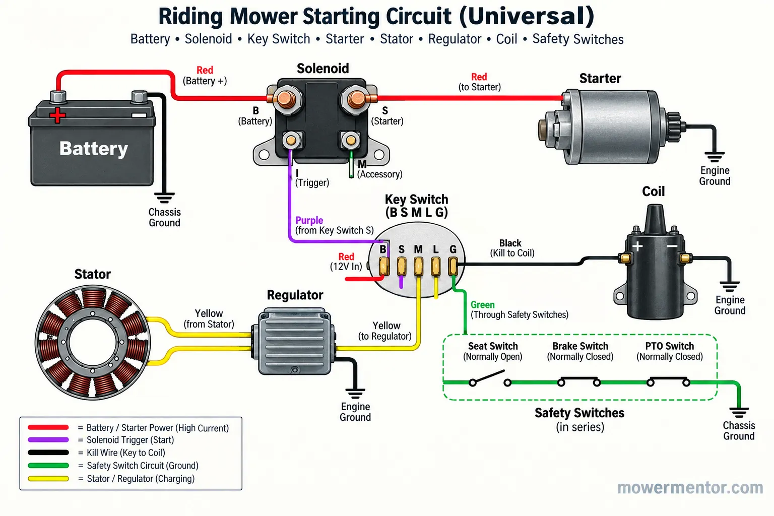
Grab the free PDF. The downloadable version at the end of this guide is the same diagram at print resolution, plus the terminal and color tables, sized to read on a phone in the yard. No email, no login, unlike the copies stuck behind sign-up walls.
A note on honesty: This is a representative diagram. Your model may route a wire differently or add a fuel-shutoff solenoid, so always confirm against your own machine before cutting or splicing.
How to Read a Lawn Mower Wiring Diagram (Every Wire, Labeled)
Reading a lawn mower wiring diagram comes down to tracing four loops rather than memorizing a maze.
According to the community answer thread on iFixit for a Craftsman rider, the core path is short: a heavy battery cable to the solenoid, a heavy output cable to the starter, and one small trigger wire from the key.
Once you can find those three wires on the page, the charging, ignition and safety loops slot in around them. That is the whole method, and it works on any brand.
Start by finding the battery, then follow the thick lines first.
Trace the heavy red cable from battery positive to the solenoid large post.
Trace the second heavy cable from the solenoid to the starter motor.
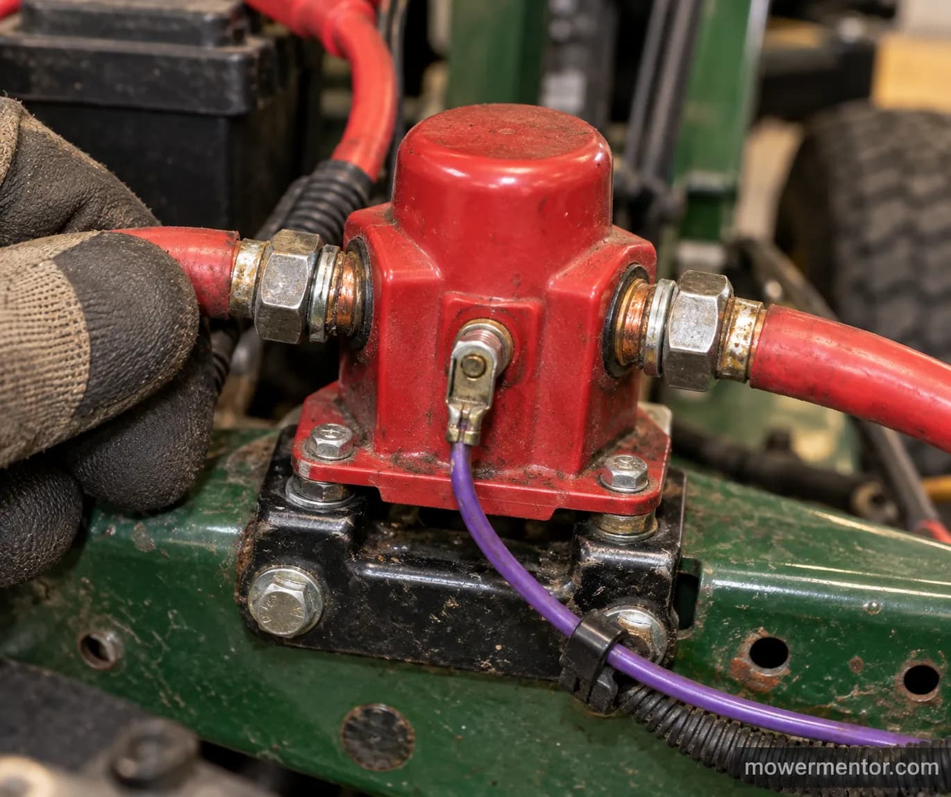
Find the thin wire from the key START terminal to the solenoid small post.
Follow the black kill wire from the key OFF path to the ignition coil.
Follow the charge wire from the stator through the regulator back to the battery.
The heavy lines carry cranking current, so they are drawn thick, while the thin lines are signals that tell heavy components when to act.
When a mower will not crank, one of the two heavy cables or that one thin trigger wire is almost always the culprit, which is why how the solenoid is wired is the first place experienced techs look.
If the heavy cables read good but nothing happens, the problem is usually upstream in the signal wiring rather than the starter itself.
In that case check whether the harness itself is damaged before condemning a part.
Only after the wiring checks out does it make sense to move on to swapping the starter motor.
From my bench: On a Craftsman with a Briggs twin, I photographed the solenoid before touching anything, and the purple wire at the small post traced straight back to the key S terminal, exactly as the universal diagram predicts. That one photo saved me from chasing the wrong cable.
Ignition Switch Terminals: B, S, M, L, G and A1
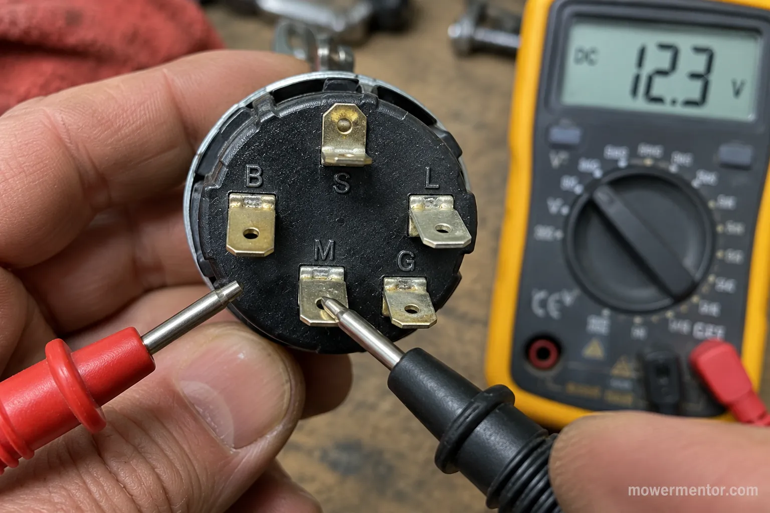
The ignition switch is the hub of any lawn mower wiring diagram, and its letters are standardized enough to memorize.
On most riding mowers B is battery, S is start, M is magneto or kill, L is lights, and G is ground, a convention echoed across repair threads including one detailed My Tractor Forum ground thread.
The A1 terminal appears on some five and six-post switches as the accessory-off ground. Knowing which terminal does what turns a confusing connector into a quick continuity check.
The table below is what I meter on the bench when a switch is suspect.
Terminal | Meaning | Hot or grounded | Active key position |
|---|---|---|---|
B | Battery feed | Always hot | All |
S | Start | Hot only in START | START |
M | Magneto / kill | Grounds the coil | OFF |
L | Lights | Hot in RUN | RUN |
G | Ground | Tied to frame | All |
A1 | Accessory ground | Grounds when off | OFF |
The behavior to remember: M is never a power terminal. It connects the coil kill wire to ground when the key is OFF, and it floats when the key is in RUN or START.
To match your own switch to these letters, a five-post map is the fastest route, so map your key-switch prongs against the terminal table above.
Brand switches vary in plug shape even when the letters match, which is why it helps to test a Craftsman key switch with a meter rather than trusting the connector alone.
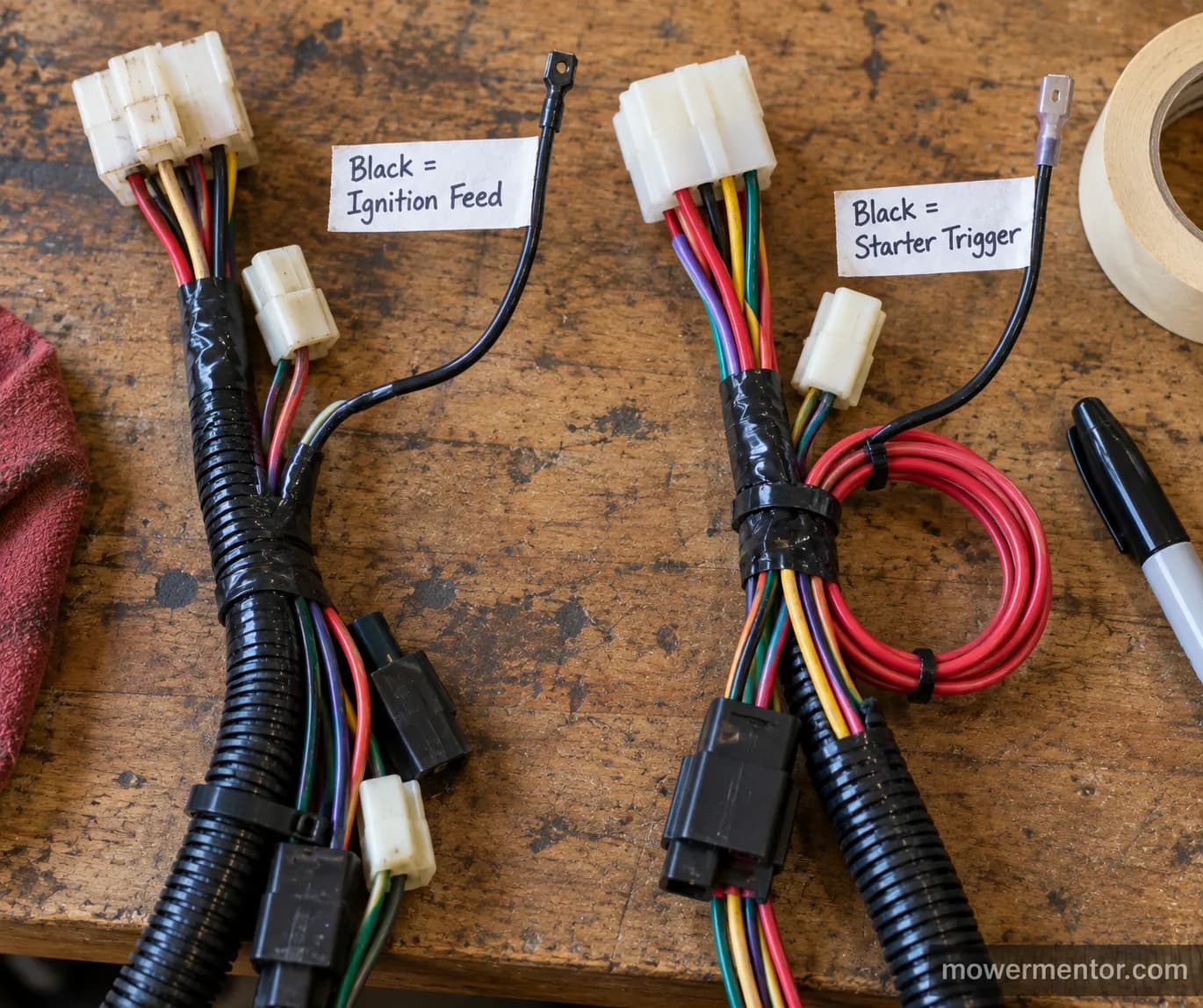
Wire Color Codes on a Lawn Mower (and Why You Cannot Trust Them)
Wire colors on a lawn mower wiring diagram are a helpful starting point and a dangerous finishing point.
The industry guide from Small Engine Warehouse states the two rules that hold most often on Briggs looms: the red wire is the DC charge lead to battery positive, and the black wire is the kill lead that runs to ground and never to positive.
Beyond those two, colors drift by brand, by model year, and by whoever replaced the harness last. Treat color as a hint and the meter as the truth.
Here is the pattern I see most often, with the honest caveat built in.
Wire color | Usual job | Confidence | Verify with |
|---|---|---|---|
Red | DC charge to battery positive | High | Voltage, key on |
Black | Coil kill / ground to frame | High | Continuity to frame |
White | Stator AC output | Medium | AC volts, running |
Yellow | Stator AC or lights | Low | AC volts, running |
Orange | Fuel shutoff solenoid | Medium | Voltage, key on |
Green | Safety switch loop | Low | Continuity, switch toggled |
The danger case is a rewired mower where someone used whatever spool they had. I have opened two Murrays in the same week where one used black for the kill wire and the other used black-with-red tracer for battery positive, so a color-only guess would have shorted the second one.
Because the switch behind those colors differs by brand, confirm the Murray key-switch wiring before you assume a color means the same thing yours does.
The Ground Wire: Coil Kill Versus Chassis Ground
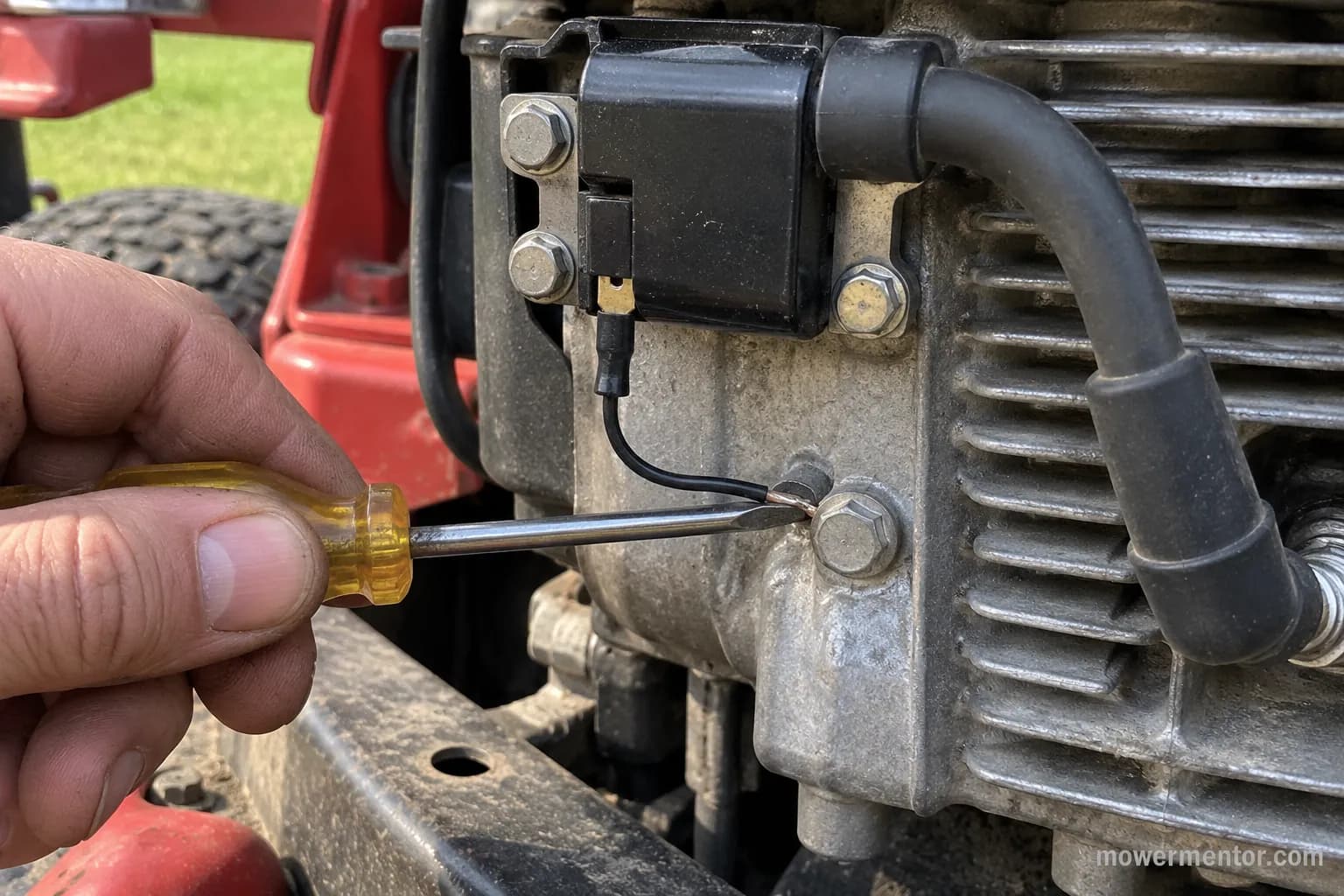
The ground wire causes more confusion on a lawn mower wiring diagram than any other conductor, because a mower has two very different grounds.
As one widely cited Lawn Mower Forum thread explains, the small black wire on the coil is a kill wire that stops the engine when the key OFF position grounds it through the switch M terminal.
The chassis ground, by contrast, is the heavy strap that returns starter current to the battery for cranking. Keep those two grounds straight and most no-spark and no-shutoff faults solve themselves.
The two conductors differ in size, path and job, as the list makes clear.
Coil kill wire: Hin, runs from the coil to the key M terminal, grounds the coil to stop spark.
Chassis ground: Heavy, bonds the engine block and frame to battery negative for cranking.
Why won't my mower shut off with the key?
If the engine keeps running after you turn the key to OFF, the kill path is broken somewhere between the coil and ground. The wire may be cut, the M terminal may have failed, or the switch itself may not be grounding.
You can prove it in seconds by shorting the coil kill lead to the engine block, which should stop the engine instantly.
To trace it end to end, follow this order.
With the engine off, disconnect the kill wire at the coil.
Set a meter to continuity between that wire and the frame.
Turn the key to OFF and confirm you read continuity.
Turn the key to RUN and confirm the continuity disappears.
If OFF does not ground, move to the switch and safety loop.
The same industry rule from the color guide applies here, that a black kill lead belongs to ground and never to battery positive, which is worth re-reading before you reconnect anything.
When a mower will not crank at all rather than refusing to shut off, the fault is a different ground entirely, so start with the no-crank, battery-to-ground checks instead.
Safety callout: Disconnect the battery negative before probing the kill circuit, and never power the coil primary directly.
A slipped probe on a live circuit can spark at the battery or damage the coil module.
Once the mower runs and shuts off cleanly, a fresh plug keeps the spark side healthy, which is a good moment to review changing a Craftsman spark plug or, on an overhead-valve Honda, dropping in a fresh Honda spark plug.
The Charging Loop: Stator, Regulator and Battery
The charging loop on a lawn mower wiring diagram is the part most owners never trace until the battery keeps dying.
Briggs & Stratton documents in its engine diagram FAQ that it publishes only generic alternator schematics, because the stator output and regulator wiring are shared across many models.
The stator under the flywheel makes AC, the regulator rectifier converts it to DC, and that DC flows back to keep the battery topped up.
A healthy loop shows roughly 13.5 to 14.5 volts DC at the battery with the engine running.
The quick test that tells you which half of the loop is bad.
Test point | Engine off | Engine running | Reading tells you |
|---|---|---|---|
Battery terminals | 12.4–12.7 V DC | 13.5–14.5 V DC | Whole loop healthy |
Stator output plug | 0 V | 20–30 V AC | Stator is making power |
Regulator DC out | 0 V | 13.5–14.5 V DC | Regulator converting |
On my test mower the battery sat at 12.5 volts off and climbed to 14.1 volts at fast idle, with about 28 volts AC at the stator plug, a classic healthy loop.
If the AC is present but the DC is not, the regulator is the failure, not the stator.
A blown charging fuse breaks this loop silently, so confirm what amp fuse it takes before you condemn the regulator.
Charging problems also ride along with general neglect, which is why a full seasonal tune-up catches many of them early.
Owners of overhead-cam engines can fold this into keeping a Honda engine tuned on the same afternoon.
Safety Interlocks: Seat, Brake and PTO Switches
The safety interlock circuit is the loop on a lawn mower wiring diagram that most often blocks a healthy starter from ever turning.
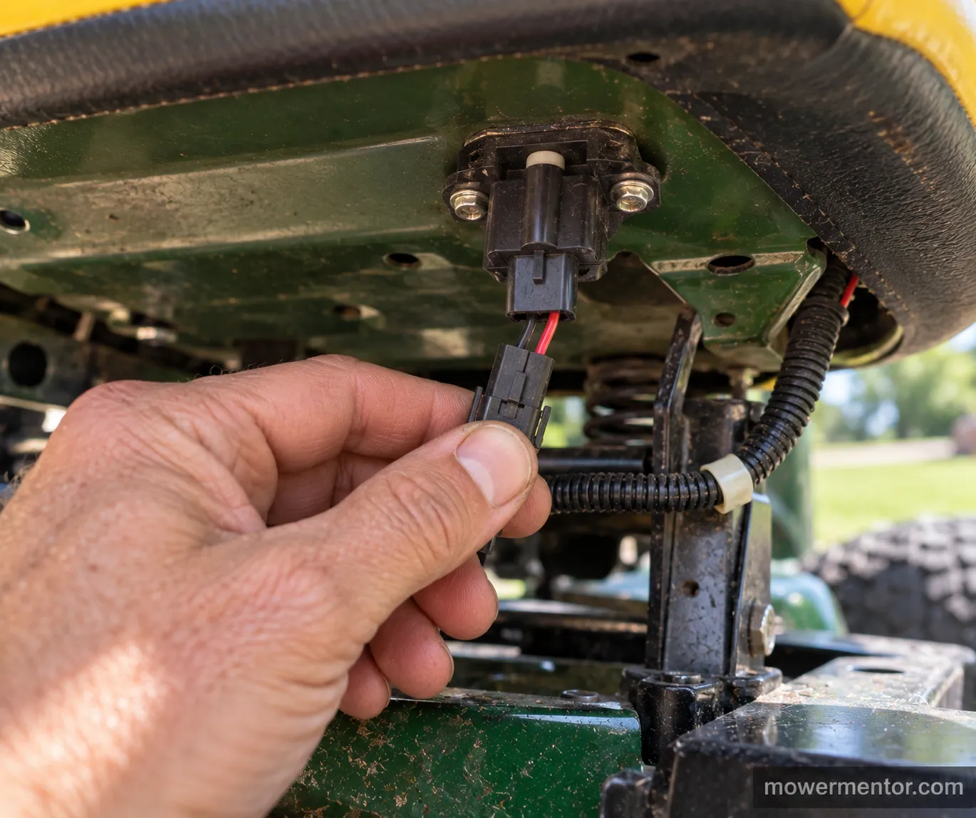
Seat, brake and PTO switches sit in the start-enable path, and the same My Tractor Forum discussion referenced earlier notes they live on the ground side, so a single unseated connector can mimic a dead battery.
Any one of those switches out of position tells the solenoid to stay open. Understanding this loop prevents a lot of needless part swapping.
The interlocks generally follow this logic on a running-and-cranking mower.
Seat switch: Must sense weight, or the engine will not crank or will kill when you rise.
Brake or clutch switch: Must be pressed to allow cranking.
PTO switch: Must be off, or the start circuit stays open.
Because the PTO switch is a frequent offender, it helps to know how the PTO switch is wired before you bypass anything.
And since a blown fuse in this loop looks identical to a bad switch, check the fuse first with a meter or test light.
From my bench: On one no-crank tractor the battery and solenoid were fine, and the fault was a seat-switch connector that had vibrated loose.
Seating it made the mower crank on the next turn of the key.
Troubleshoot Any No-Start With the Diagram
Troubleshooting with a lawn mower wiring diagram means letting the noise the mower makes point you to the right loop.
A single loud click, rapid clicking, or dead silence each map to a different spot on the diagram, so you test one node instead of guessing.
This is where the universal diagram earns its keep, because it turns a vague no-start into a short list of measured checks.
Work the loops in the order the current flows and you rarely replace a good part.
The sound-to-cause map I use most.
Symptom | Likely loop | First measurement |
|---|---|---|
Nothing, no click | Start signal or interlock | 12 V at solenoid small post in START |
Single loud click | Solenoid or starter | Voltage across solenoid large posts |
Rapid clicking | Weak battery or ground | Battery voltage under load |
Cranks, no spark | Kill circuit | Continuity of kill wire to ground |
Runs, will not stop | Kill circuit open | Continuity at M terminal in OFF |
Put a test light on the solenoid small post and turn to START. If it lights but the solenoid does nothing, the solenoid or starter is the fault.
If it stays dark, the signal never arrived, and the interlock or key switch is the fault.
For the complete branch-by-branch tree beyond these first checks, follow the full no-start diagnosis.
If your checks point at the starter, bench-test the starter off the mower to confirm before buying one.
Murray owners chasing an intermittent crank can follow the model-specific Murray starting-fault walkthrough.
Brand Notes and Where to Get Your Model's Diagram
Brand-specific wiring is where a universal lawn mower wiring diagram hands off to the manufacturer.
Briggs & Stratton and Vanguard both confirm they supply only generic alternator schematics, with Vanguard's electrical schematic FAQ directing owners to the original equipment maker for a model-specific diagram.
That means the engine brand and the mower brand are two different sources, and you often need both.
The universal diagram gets you 90 percent of the way, and the model sheet fills the last 10 percent.
Where each brand actually keeps its diagrams.
Brand | Where the diagram lives | Notes |
|---|---|---|
Craftsman | Model manual on Sears Parts Direct | Search the full model number |
John Deere | Operator and technical manuals | Some behind dealer access |
Husqvarna | Model IPL and owner's manual | Fuse and harness detail included |
Cub Cadet | Support portal by model | Often a gated PDF |
Briggs / Kohler engines | Generic alternator schematics | Engine side only, not the mower |
Because engine and chassis wiring interleave, the Husqvarna fuse-and-wiring specifics are worth reading alongside the engine sheet.
Craftsman owners can match harness plugs using Craftsman diagrams by model.
And since electrical faults often surface during service, John Deere owners can pair this with tuning up a John Deere.
Trust callout: We cannot host copyrighted factory diagrams here. What this guide provides is the universal circuit plus an honest directory of where each brand's own diagram is published.
Free Lawn Mower Wiring Diagram PDF and FAQ
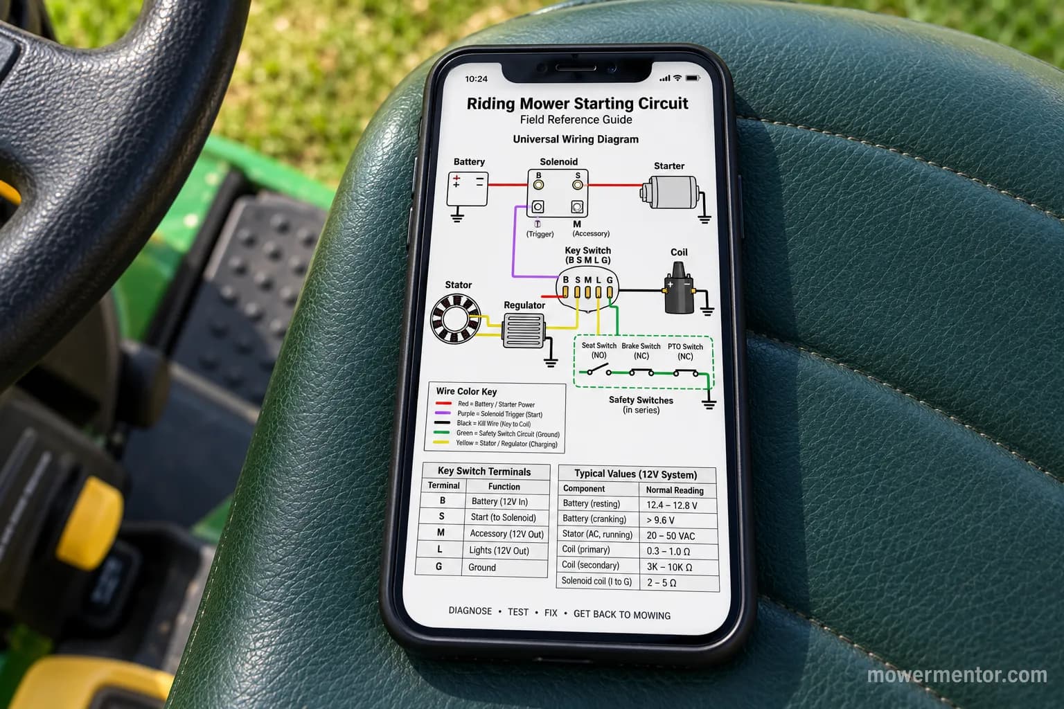
The free lawn mower wiring diagram PDF packages everything above into one printable, phone-friendly reference with no login required.
It includes the universal starting-circuit diagram, the ignition-terminal table, the color table with its verify-first caveats, and the sound-to-cause troubleshooting map.
Unlike the copies locked behind document-sharing sign-up walls, this one downloads directly. Print it, fold it into the mower manual, and keep it where the work happens.
Frequently Asked Questions
Are all lawn mower wiring diagrams the same?
No, but they share one universal starting circuit: the battery, solenoid, starter, key switch and coil kill wire are wired the same way across most riding mowers, while fuse placement, colors and safety-switch count vary by model. Learn the universal circuit first, then use your model sheet for the last details.
What is the small wire on the ignition coil?
That is the kill wire, and it stops the engine by grounding the coil: when the key turns to OFF, the M terminal connects that wire to the frame and kills the spark. If the wire is cut or the terminal fails, the engine will keep running with the key off.
How do I read the ignition switch terminals?
Use the letters stamped near each terminal: B is battery, S is start, M is magneto or kill, L is lights, and G is ground, where B is always hot, S is hot only in START, and M grounds the coil in OFF. A meter set to continuity confirms each one in seconds.
Can I trust the wire colors on my mower?
Only as a starting hint: red is almost always the DC charge lead and black is almost always the kill or ground lead, but everything else drifts by brand, year and prior repairs. Confirm any color with a multimeter before you cut or connect.
Where do I find the exact diagram for my model?
Check two sources: the mower brand's model manual for the chassis wiring, and the engine maker for the generic alternator schematic. The engine brands publish only generic electrical sheets and point you to the mower manufacturer for a model-specific diagram.
Putting the Diagram to Work
A lawn mower wiring diagram stops being intimidating the moment you see it as four short loops sharing one battery and one ground.
Trace the heavy cables, find the one thin trigger wire, respect the coil kill wire, and check the safety switches, and most riding-mower electrical faults resolve without guessing.
Keep the free PDF on your phone so the picture is always in reach when the key turns and nothing happens.
The next time a mower goes silent, you will read the circuit instead of fearing it.
Read it your way
Short on time? Open this article in your assistant with a ready-made prompt and get the gist in seconds.
Found this useful? Make us a preferred source so we show up in your Google results.
Keep reading
Related articles
Troubleshooting & Repair
Lawn Mower Ignition Switch Replacement (Steps + Cost)
Do your own lawn mower ignition switch replacement: photo steps, wire-by-terminal transfer, fitment help, and a DIY-vs-shop cost table to save $100+.
Troubleshooting & Repair
Which Lawn Mower Ignition Switch Fits? (Prong Guide)
hoose the right lawn mower ignition switch by prong count (4/5/6/7), universal vs OEM fit, and key compatibility, plus which one fits your mower.
Troubleshooting & Repair
How to Start a Lawn Mower With a Bad Ignition Switch
Confirm it's the switch, then learn how to start a lawn mower with a bad ignition switch: a safe solenoid bypass to get moving, plus how to fix it for good.
Troubleshooting & Repair
How to Test a Lawn Mower Ignition Switch (5/6/7-Pin)
Learn how to test a lawn mower ignition switch with a multimeter: get continuity tables for 5, 6 & 7-pin switches plus a no-multimeter test-light method.
The discussion
Comments
Every comment is reviewed before it goes live.