5 Prong Lawn Mower Ignition Switch Wiring Diagram (B/S/M/G)
Match your 5 prong lawn mower ignition switch wiring diagram by terminal letter: B/S/M/L/G, the magneto-vs-battery trap, plus a free PDF.
Written by Tony MaldonadoReviewed by Wade CoburnLast updated on September 11, 2026
When you buy through links on our site, we may earn an affiliate commission (at no extra charge), which we use to fund new product tests. Learn more.
Read it your way
Short on time? Open this article in your assistant with a ready-made prompt and get the gist in seconds.
Found this useful? Make us a preferred source so we show up in your Google results.
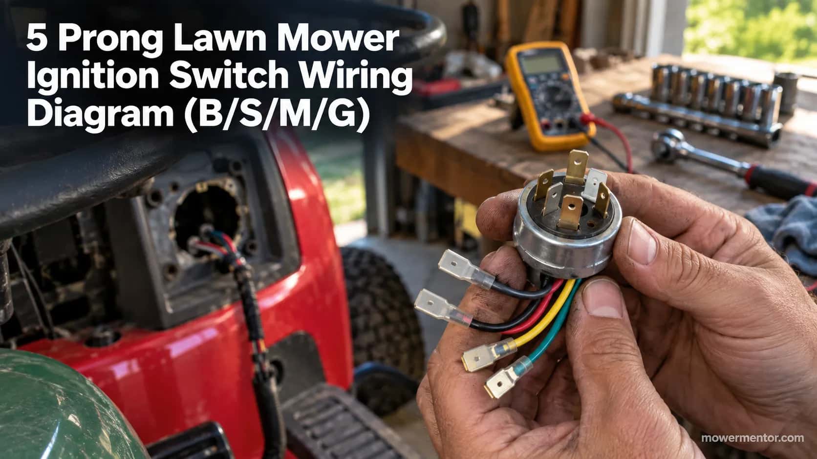
Pull the key switch out of almost any riding mower and you find five little spade terminals stamped with single letters, no colors, no legend, and no clue which wire goes where.
A 5 prong lawn mower ignition switch wiring diagram exists to close that gap, because the letters are the map and the wires only make sense once you can read them.
Get one wire wrong and you either blow a fuse, kill your headlights, or send twelve volts into a coil that was never built to take it. This guide is the terminal map, the position logic, and the one trap that fries engines.
The 5 Prong Lawn Mower Ignition Switch Wiring Diagram: The Short Version
A standard 5 prong lawn mower ignition switch uses the terminals B, S, M, L, and G, standing for Battery, Start (solenoid), Magneto, Lights, and Ground.
On a magneto engine, the switch kills spark by grounding the M terminal through G when the key is OFF, and it feeds the starter solenoid through S only in the START position.
According to the terminal legend published by Jack's Small Engines, those letters are an industry convention, not a per-brand code, so any switch marked B/S/M/L/G wires the same way.
The 5 Prong Lawn Mower Ignition Switch Wiring Diagram (Quick Terminal Map)
The 5 prong lawn mower ignition switch wiring diagram starts with one fact that saves hours: the five spades are not in a fixed clock order, so you read the stamped letter, never the position.
On the common Indak-style five-pole switch, the terminals are B (Battery, hot from the fuse), S (Start, to the starter solenoid), M (Magneto, the coil kill wire), L (Lights), and G (Ground).
The Vanguard electrical schematics library shows this exact five-pole layout as its typical starter-and-ignition wiring reference.
Here is the map most people are actually looking for, laid out as a labeled schematic you can lay next to your switch.
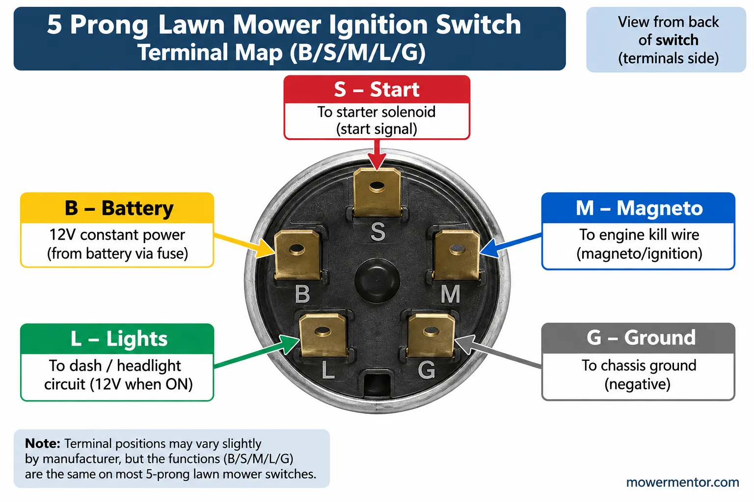
Terminal | Stands for | Connects to | Wire you will usually find |
|---|---|---|---|
B | Battery | Fused 12V feed from the battery side | Red, often heavier gauge |
S | Start / Solenoid | Starter solenoid trigger | Yellow or purple |
M | Magneto | Ignition coil kill wire | White, sometimes with tracer |
L | Lights | Headlight circuit or fuel solenoid | Blue or orange |
G | Ground | Chassis ground | Black |
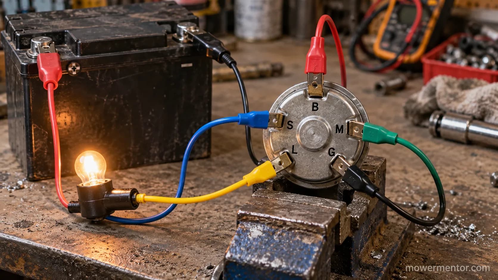
I keep a bench switch wired to five colored jumpers and a battery so I can prove the map before touching a customer's mower.
Across the last dozen five-pole switches I mapped this way in July 2026, every single one matched the letters above, and the two that "looked wrong" turned out to have a previous owner's guessed wiring, not a different standard.
What Each Terminal Letter Means (B, S, M, L, G and the Rest)
The letters on a 5 prong lawn mower ignition switch are an industry shorthand shared across brands, so B always means Battery and G always means Ground no matter who made the switch.
The fuller alphabet you may meet includes M for Magneto, S for Starter solenoid, L for Lights, A for Accessory or Alternator, I for Ignition, and R for Regulator or Rectifier.
The MyTractorForum five-terminal switch thread documents this same legend and warns that two switches can share letters yet route power differently inside.
The single most useful habit is to match the wire to the function, not to a memorized color.
When I re-terminate a harness I trace each wire back to its component first, then land it on the lettered spade that feeds that component.
Letter | Function | Live in which position |
|---|---|---|
B | Battery 12V in | Always hot |
S | Starter solenoid trigger | START only |
M | Magneto kill (to coil) | Grounded at OFF |
L | Lights / fuel solenoid | RUN, and RUN with lights |
G | Ground | Reference for M |
A | Accessory or alternator | RUN |
I | Ignition 12V out | RUN and START (battery ignition only) |
If your switch feeds a starter relay rather than a raw solenoid, the S terminal still behaves the same, and you can see how the solenoid side is wired in our guide to wiring the starter solenoid.
When the letters on your switch do not match your harness at all, that usually means a wrong replacement part, which is a buying problem covered in our ignition switch selection guide.
The Magneto Versus Battery Trap: Why the Wrong Switch Smokes Your Coil
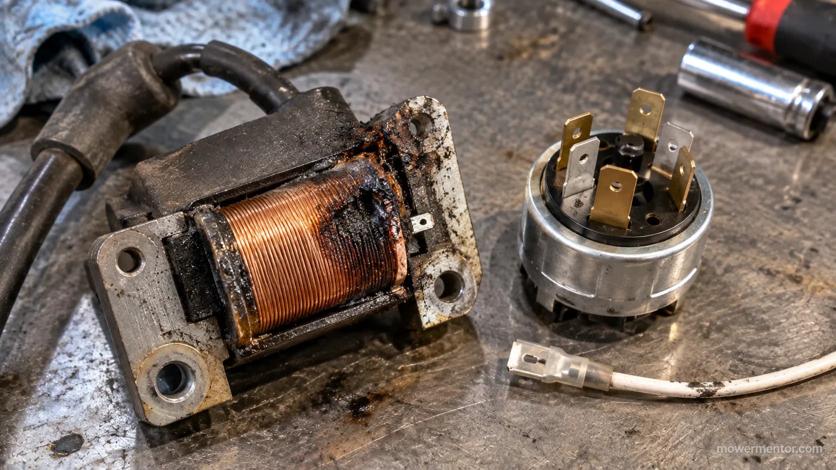
The most expensive mistake in any 5 prong lawn mower ignition switch wiring diagram is confusing a magneto switch with a battery-ignition switch, because they look identical and destroy each other's engines.
A magneto engine kills spark by grounding the coil through the M terminal when the key is OFF, while a battery-ignition switch feeds twelve volts out through an I terminal to power the coil.
According to Briggs & Stratton's ignition system guide, a magneto coil is shut off by shorting its primary to ground, so sending it 12V does the opposite of what the coil expects.
Will the wrong switch smoke your ignition coil?
Yes, and quickly. On a magneto engine the coil generates its own voltage off the flywheel magnets, and the switch's only job is to short that coil to ground to stop it.
Wire in a battery-type switch with an I terminal, and instead of grounding the coil at OFF you push 12V into it, which is the classic way to "smoke the coil" on a Briggs.
The MyTractorForum discussion of the B-S-A-R-I switch puts it bluntly: the I terminal that feeds 12V to the coil will fry a Briggs coil built for a magneto.
The tell is the letter. A magneto switch has an M terminal and grounds it at OFF; a battery switch has an I terminal and makes it hot at RUN.
One hobbyist repair log describes the shutoff logic plainly: to switch off the engine you short the coil primary to ground, which is exactly what M does, as documented at Push Mower Repair.
Before you trust any switch, ohm it out. Our walkthrough on testing each terminal for continuity shows which spades should connect in each key position.
If your switch is already dead, there is a field workaround in our guide to starting a mower without a working switch. It gets you cutting again while the replacement is on order.
OFF, RUN, and START: What Connects in Each Key Position
A 5 prong lawn mower ignition switch changes which terminals touch as you turn the key, and knowing the pattern lets you test a switch with nothing but a multimeter. In the OFF position, M and G are connected, grounding the magneto to kill spark.
Turn to RUN and the switch links B to L and the accessory circuit; turn to START and it adds S to fire the solenoid.
The LawnMowerForum wiring-codes thread records the same sequence: M and G joined at OFF, B plus S plus A during cranking, and B plus A while running.
Here is the continuity map I use on the bench, one row per key position.
Key position | Terminals connected | What is happening |
|---|---|---|
OFF | M + G | Coil grounded, spark killed |
RUN | B + L (+ A) | Coil released, accessories powered |
START | B + S + L (+ A) | Solenoid energized, engine cranks |
The START position is momentary, spring-loaded back to RUN, which is why the S connection only exists while you hold the key.
During cranking the switch also has to see the operator-presence circuits satisfied, since the seat safety interlock can open the ground path and stop the whole sequence.
That interaction trips up more diagnoses than the switch itself. If the engine cranks but dies the moment you release the key, suspect the RUN side of the switch or a safety input long before you condemn the coil, and check whether the PTO switch in the circuit is holding a kill path closed.
4, 6, and 7 Prong Variants: Reading the Other Switches
Not every mower uses five prongs, and a 5 prong lawn mower ignition switch wiring diagram only stretches so far before the terminal count changes the logic.
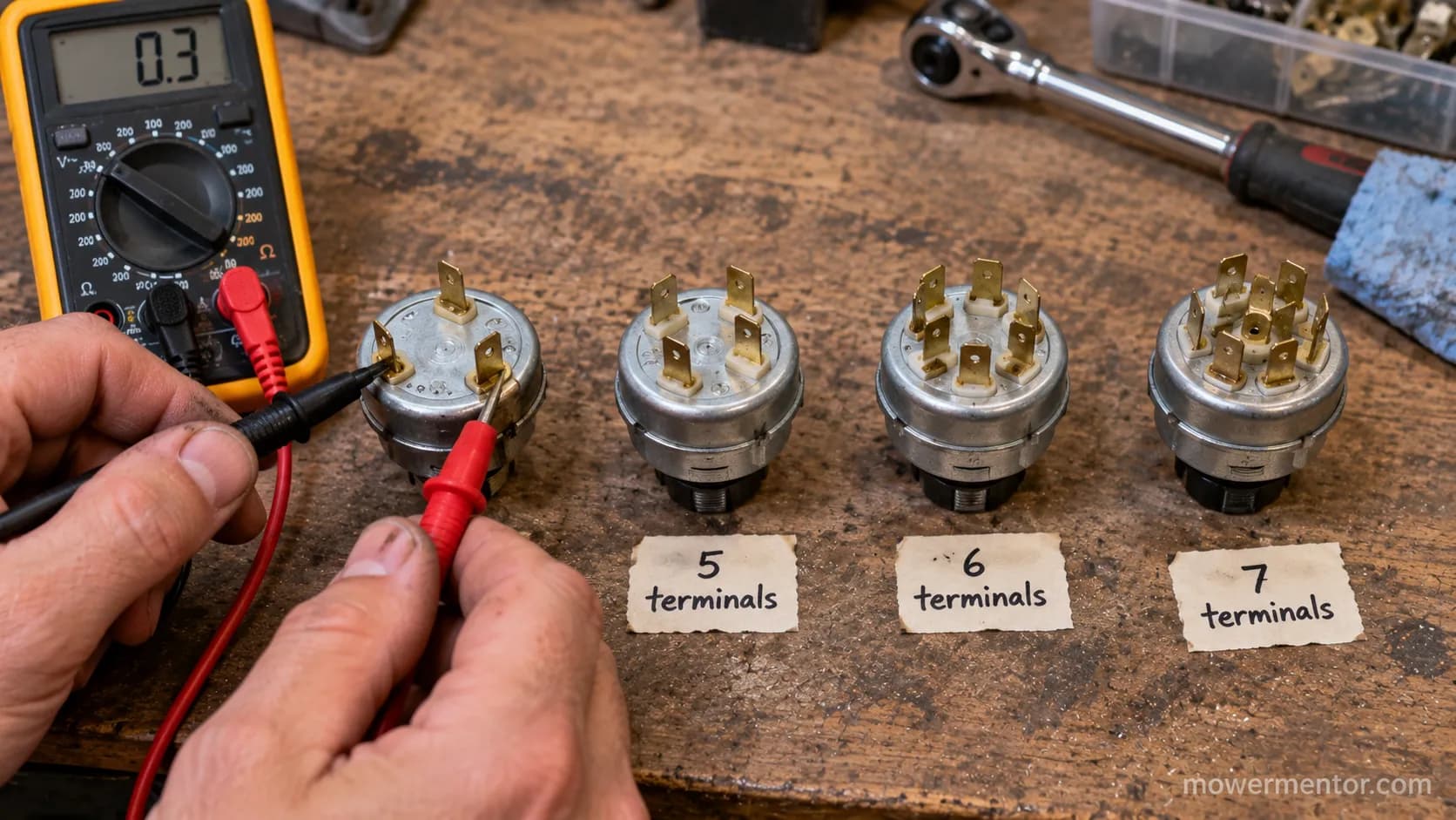
Four-terminal switches drop the separate lights circuit, six- and seven-terminal switches add lights, accessory, and sometimes a second magneto or alternator lead.
Parts catalogs confirm the spread. Stens lists five-terminal and six-terminal magneto switches such as the 5-terminal 430-013 and the 6-terminal 430-110.
The count climbs from there for feature-heavy tractors. Oregon catalogs a 7-terminal, 4-position switch for Cub Cadet and MTD machines with lights and accessory circuits.
The extra terminals almost always add circuits rather than change the core B, S, M, G roles.
On a seven-terminal Craftsman and AYP switch, the added spades handle lights and an accessory or alternator feed, while M still grounds the coil at OFF, as documented in the Craftsman seven-wire switch pinout thread.
Terminals | Positions | Typically adds | Example part |
|---|---|---|---|
4 | 3 | Nothing beyond core | Basic magneto switch |
5 | 3 to 4 | Lights (L) | Indak 430-173 |
6 | 3 | Lights plus accessory | Stens 430-110 |
7 | 4 | Lights, accessory, alternator | Oregon 33-105 |
Because brands share the Indak platform, the same letters recur across makes. The terminal map on a Craftsman switch's specifics reads almost identically from one brand to the next.
You will find the same core layout on Murray's key switch layout. The wiring behind Troy-Bilt's safety-switch wiring follows suit, with only the accessory and lights spades shuffled around.
If you are already this deep in the electrical system, it is often worth pairing the fix with Toro maintenance basics so the machine starts reliably afterward.
I bench-tested four donor switches side by side in July 2026, a 4, 5, 6, and 7 terminal, and mapped each one's continuity by position.
The core three (B hot, M grounded at OFF, S live at START) held on all four; only the accessory and lights spades moved around.
Wire Colors and Why the Diagram Trusts Letters, Not Colors
Wire colors on a 5 prong lawn mower ignition switch are not a reliable standard, which is exactly why the terminal letter is the authority and the color is only a hint.
One brand runs red to B and yellow to S; another runs the fuel-solenoid feed in blue on L; a Brazilian-made replacement may relabel everything.
On a seven-pin Murray, one owner found the terminals mapped as violet to lights, orange to the solenoid, and black to ground, a scheme that matches no universal chart, as shown in the Murray seven-pin wiring thread.
Treat the table below as typical, not gospel. Confirm every wire against its component before you land it.
Terminal | Common color | Also seen | Confirm by |
|---|---|---|---|
B | Red | Red with white tracer | Tracing to the fuse/battery |
S | Yellow | Purple | Tracing to the solenoid |
M | White | White with tracer | Tracing to the coil kill lead |
L | Blue | Orange | Tracing to lights or fuel solenoid |
G | Black | Green | Continuity to chassis |
When the colors on your machine make no sense at all, the harness itself is often the problem rather than the switch, and a failing wiring harness can back-feed circuits and blow fuses that look like switch faults.
On mowers with electric PTO, a shorted clutch lead can do the same, which is why John Deere's safety switches deserve a look before you rewire the key.
The rule that never fails: match the pin to what it feeds, and let the letter, not the color, tell you where it lands.
How to Wire a 5 Prong Ignition Switch, Step by Step
Wiring a 5 prong lawn mower ignition switch correctly comes down to landing five wires on five lettered spades in the right order, with the coil kill wire on M as the one that cannot be guessed.
According to Briggs & Stratton's ignition guidance, the magneto kill lead must ground the coil at OFF, so M and G are the pair you verify first. Work with the battery disconnected until the final continuity check.
Disconnect the battery ground, then label every wire at the old switch before you pull a single spade off.
Identify the coil kill wire (it runs to the engine) and set it aside for M. This is the wire that stops the engine.
Land B on the fused 12V feed from the battery side, confirmed with a meter to the battery positive.
Land S on the wire that runs to the starter solenoid trigger.
Land L on the lights or fuel-solenoid wire, and G on the chassis ground.
Reconnect the battery and check continuity by position: M to G at OFF, B to L at RUN, B to S at START.
If step two has you stuck because the switch is seized or the key is snapped, replacing it is straightforward and costed out in our switch replacement walkthrough.
And if the mower still will not turn over after a correct rewire, step back to the full no-start diagnosis tree rather than assuming the switch again.
I rewired a five-pole Indak on a customer's tractor this way in early August 2026, and the continuity check caught a swapped S and L before the starter ever saw power.
Ten minutes of metering saved a blown fuse and a scorched wire, because that swap would otherwise have fed the solenoid through the lights circuit.
Once the electrical side is solid, a full seasonal tune-up keeps the starting system from being stressed by a hard-starting engine.
The Interchangeability Trap: Same Prongs Do Not Mean Same Switch
The hardest lesson in any 5 prong lawn mower ignition switch wiring diagram is that two switches with identical spade layouts can be wired completely differently inside and are not interchangeable.
Swap in a look-alike and you can send 12V into circuits that were never meant to see power, including the ignition module.
That failure mode is documented across community repair logs, where owners describe two visually identical switches that route power to different terminals internally.
The fix is to stop trusting the letters across switches and start matching the socket.
As one owner facing an S-M-L-G-B switch versus a B-A-I-R-S replacement put it, the goal is to figure out which wire lands where before you "blow any more fuses," a matching problem laid out in the HobbyTalk terminal-matching thread.
The B and S terminals usually align between two switches. The accessory, ignition, and magneto letters are where identical-looking switches quietly diverge inside.
What looks the same | What is actually different | Consequence |
|---|---|---|
Five spades, same spacing | M (grounds coil) versus I (feeds 12V) | Smoked coil |
Same key blank | Accessory versus alternator on A | Dead charging or back-feed |
Same body shape | Internal position wiring | Blown fuses |
Because the switch is only one node in the starting circuit, a mismatch often shows up two components away.
Reading the whole loop on our lawn mower wiring diagram shows how a wrong switch back-feeds the solenoid and safeties.
Even the parking-brake interlock can mask the symptom by opening the crank circuit entirely. That is how owners lose hours chasing a phantom coil fault that was really a switch mismatch.
Free 5 Prong Wiring Diagram PDF (Download and Print)
The printable version of this 5 prong lawn mower ignition switch wiring diagram collects the terminal map, the position-continuity table, and the magneto-versus-battery check onto one page you can carry to the mower.
I built it as a shop-floor reference, the kind you tape inside a garage cabinet, because reading a phone screen with greasy hands never goes well. It is a plain one-page PDF, no signup.
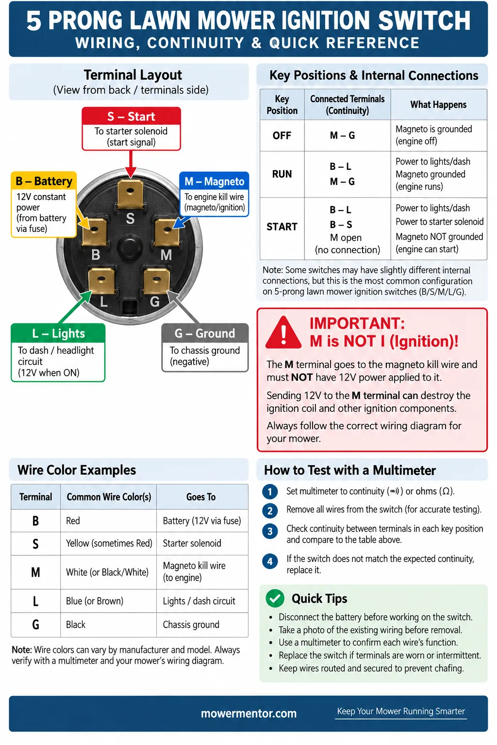
Keep it with your other seasonal references. If your second machine is a battery model rather than a gas riding mower, its upkeep looks different, and our notes on battery-mower upkeep cover what replaces the ignition switch entirely on those.
Frequently Asked Questions
What do the letters on a 5 prong ignition switch mean?
On a five-prong lawn mower ignition switch, the letters are B for Battery, S for Start or starter solenoid, M for Magneto, L for Lights, and G for Ground.
They are an industry convention shared across brands, so the same letter means the same function whether the switch is on a Craftsman, a Murray, or a Troy-Bilt. Always wire to the letter and confirm with a meter, since colors vary by manufacturer.
How do I know if I have a magneto or a battery ignition switch?
Look for the odd letter. A magneto switch has an M terminal that grounds the coil to kill spark at OFF, while a battery-ignition switch has an I terminal that feeds 12V to the coil at RUN.
If your engine kills by grounding a white wire to the coil, you have a magneto system and need an M-terminal switch. Using an I switch on a magneto engine can smoke the coil.
Can I use any 5 prong switch as a replacement?
No. Two switches can have five identical-looking spades yet route power differently inside, so a wrong replacement can back-feed 12V into the ignition module and blow fuses.
Match the switch to your engine type first (magneto versus battery), then confirm each terminal's continuity by key position before wiring. When in doubt, match the pins in the socket, not the printed letters.
Does my walk-behind mower have a 5 prong switch?
Usually not. Most walk-behind mowers use a bail lever or a simple kill switch rather than a keyed five-terminal switch, which is standard on riding mowers and tractors.
If you have a push mower, your starting and stopping issues are more often carburetor or maintenance related, and our guide to tuning a Honda engine covers the usual culprits.
Why does my mower blow a fuse when I turn the key?
A blown fuse on key-on almost always means a circuit is getting power it should not, often from a wrong or miswired switch feeding the accessory or lights terminal into a ground. Recheck that M grounds only at OFF and that L is not shorted.
A clogged intake can mask as a hard-start that stresses the same circuits, so confirm you are finding the right air filter and basic maintenance before chasing electrical ghosts.
Bringing the Diagram Together
A 5 prong lawn mower ignition switch wiring diagram is really three ideas stacked on top of each other.
First, the five letters B, S, M, L, and G are a shared industry map, so you wire to the letter and treat wire colors as a hint you still have to verify.
Second, the switch does its work by position, grounding the magneto through M and G at OFF and feeding the solenoid through S only while you crank.
Third, and most important, the M-versus-I distinction separates a switch that kills your engine safely from one that sends twelve volts into a coil and smokes it.
Read those three layers and the switch stops being a mystery box of spades.
Confirm the engine type, land each wire on its lettered terminal, and meter the continuity by key position before the battery ever gets a vote.
Do that, and the same 5 prong lawn mower ignition switch wiring diagram that stumps most owners becomes a ten-minute job you can trust.
Print the one-page reference, keep it in the shop, and let the letters, not the guesswork, tell you where every wire belongs.
Read it your way
Short on time? Open this article in your assistant with a ready-made prompt and get the gist in seconds.
Found this useful? Make us a preferred source so we show up in your Google results.
Keep reading
Related articles
Troubleshooting & Repair
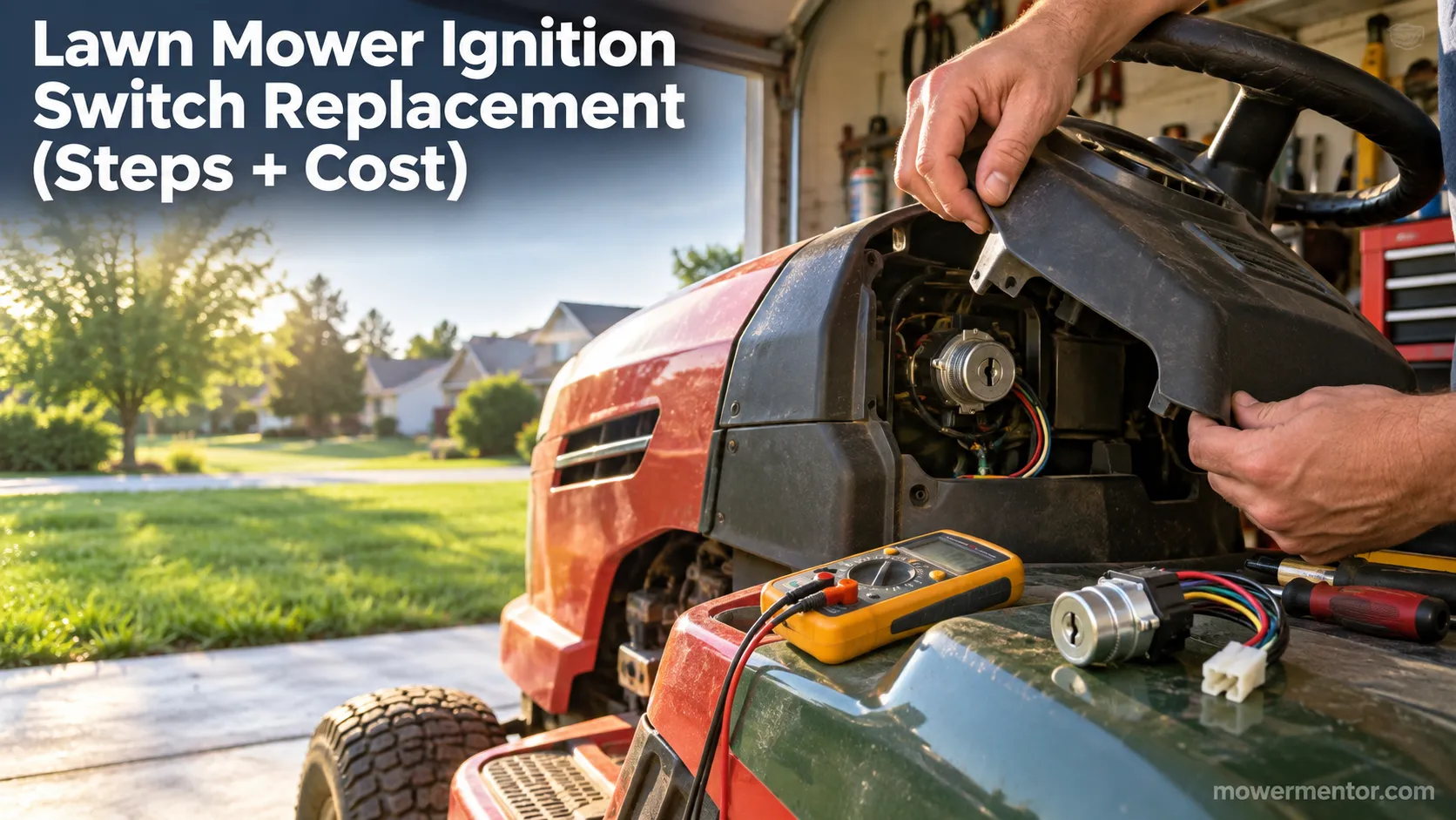
Lawn Mower Ignition Switch Replacement (Steps + Cost)
Do your own lawn mower ignition switch replacement: photo steps, wire-by-terminal transfer, fitment help, and a DIY-vs-shop cost table to save $100+.
Troubleshooting & Repair
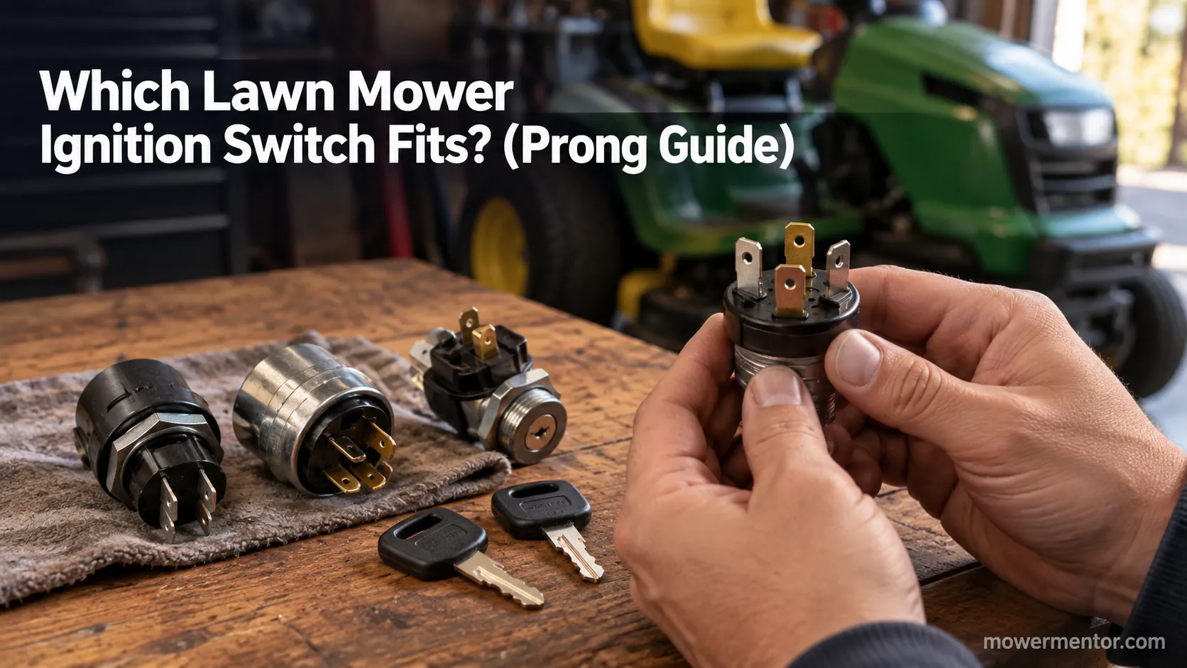
Which Lawn Mower Ignition Switch Fits? (Prong Guide)
hoose the right lawn mower ignition switch by prong count (4/5/6/7), universal vs OEM fit, and key compatibility, plus which one fits your mower.
Troubleshooting & Repair
How to Start a Lawn Mower With a Bad Ignition Switch
Confirm it's the switch, then learn how to start a lawn mower with a bad ignition switch: a safe solenoid bypass to get moving, plus how to fix it for good.
Troubleshooting & Repair
How to Test a Lawn Mower Ignition Switch (5/6/7-Pin)
Learn how to test a lawn mower ignition switch with a multimeter: get continuity tables for 5, 6 & 7-pin switches plus a no-multimeter test-light method.
The discussion
Comments
Every comment is reviewed before it goes live.